Egersund Basin case study
Geological model
The main target for CO2 injection is the extensive middle Jurassic sands of the Sandnes and Bryne Formations in the Egersund Basin southwest of Stavanger. The Egersund Basin is a local deepening between the Norwegian-Danish Basin and the Stavanger Platform in the North Sea. The southern part of the basin is the focus for this study. The Egersund Basin has a small local oil kitchen to the NW, charging the Yme Field which is situated in the northern part of the basin. The development of lower and middle Jurassic sandstones is partly influenced by the tectonic structuring and salt movement. Later, the upper Jurassic – Lower Cretaceous tectonic development created a series of NW-SE faults. In the late Neogene the basin was lifted obliquely east-ward and up towards the Norwegian mainland. This is a promising area with good reservoir sand, well suited for containment of substantial volumes of CO2. Migration of CO2 into to salt structures penetrating the post Permian sequences and further into the Neogene, should however be avoided.
The Sandnes Formation contains marine sands with a high net/gross ratio, whereas the underlying Bryne Formation represents continental sand deposits with marine incursions. The lateral and vertical communication of the Bryne Formation is considered to be uncertain, and consequently it is not as suitable for large scale CO2 injection. However, the Bryne Formation and some of the upper Triassic sands will contribute to the active aquifer volume. The reservoir sands are sealed by thick Jurassic and Cretaceous shales.
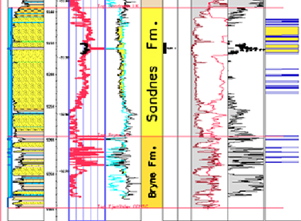
Fig-4-115
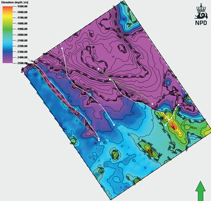
Fig-4-116
The simulated part of the Egersund Basin area.
Results from the reservoir simulation of the Egersund Basin.
A segment model (48km x 62km) of the Egersund Basin was contructed to estimate the storage capacity and the migration paths. Different cases were run with 1-3 injection wells and injection rates from 2 to 10 MSm3 CO2/year in 50 years. Bottomhole pressure change is limited to 30 bar. Faults in the model were simulated with open and closed scenarios. Results showed that the volume of CO2 injected is not very different between open and closed faults cases, but the distribution of the CO2 plume is different (se figure).
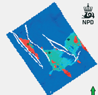
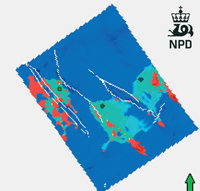
Fig-4-117
CO2 distribution after 1000 year from injection start. With closed faults (left), and open faults (right). A part of the CO2 migrates through the faults to the west.
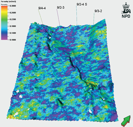
Fig-4-118
Porosity map of the uppermost layer of the Sandnes Formation used in the simulation
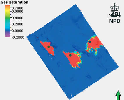
Fig-4-119
CO2 distribution after 50 years injection in three wells.
Conclusion
Using the model and relative permeability curves from the Frigg field with a residual CO2 saturation of 0.3, the storage capacity is:
- 180 GSm3 or 0.36 Gigatons assuming a reservoir pressure buildup of 9 bar with 1 injector
- 546 GSm3 or 1.1 Gigatons assuming a reservoir pressure buildup of 26 bar with 3 injectors