Stord basin - long distance CO2 migration
Modelling of CO2 injection and migration in the Stord basin. The aquifers in the eastern part of the North Sea typically have a consistent dip of about one degree from the Norwegian coast down to the basinal areas. In the case that there are permeable beds along this dip slope, there is a risk that CO2 injected in the downdip aquifer can migrate up to where the aquifer is truncated by Quaternary glacial sediments. At that depth, the CO2 will be in gas phase. The glacial sediments mainly consist of clay and tills and their thickness ranges from about 50 m and up to more than 200 m (figure). Understanding the timing and extent of long distance CO2 migration is of importance for the evaluation of the storage capacity of outcropping aquifers. Consequently, a modelling study was set up on a possible aquifer in the Stord Basin.
The Stord Basin is bordered by faults between the Utsira High in the west and the Øygarden fault complex in the east. The syn-rift basin acted as a depocentre for infilling sediments from all surrounding highs, the main source being the eastern hinterland. The basin is overlain by postrift sediments ranging from late Jurassic to Quaternary age. Sand is mainly found in the Triassic and Jurassic. The main risks of leakage of injected CO2 in the Stord basin area are sideways migration towards the east, and migration along fault planes. Absence of syn-rift sedimentary rocks on the upthrown side of the Øygarden fault complex may reduce the risk of sideways migration in this section.
A simulation model of a possible Upper Jurassic sand deposit (referred to as Sandy delta in the cross section) was built based on a geological model derived from seismic interpretation. The model shown in the figure has been used to simulate CO2 injection in the sand deposit, which will act as an aquifer.
The modeled depositional system has not been drilled, and the interpretation is based on seismic 2D data. Although there is a reservoir risk in this particular model, the results can be applied to analogous aquifers with gentle dips.
Three injection wells are shown in the areas with highest permeability (green). A water producer is located on the east side of the grid, acting as a leaking point in the shallowest part. The permeability and porosity distribution around well 1 is shown in the profiles. The model was run with 50 years of injection with different rates. After shut-in of injection, migration continued until the CO2 had migrated up to the east side of the model and begun to enter the Quaternary formations above. The simulations were run with one, three and five wells.
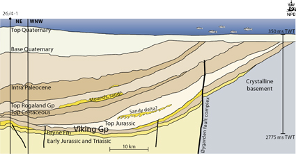
Fig-4-088
Seismic panel including well 26/4-1, Stord basin
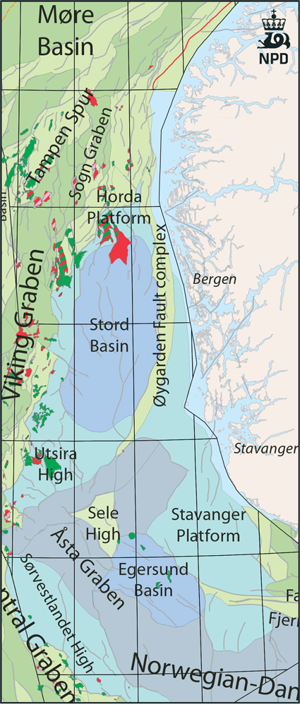
Fig-4-089
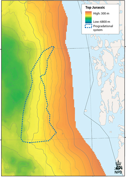
Fig-4-090
Polygon depicting modelled aquifer
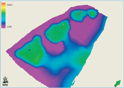
Fig-4-091
Permeability in upper layer 1
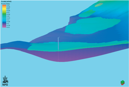
Fig-4-092
Porosity distribution near well 1
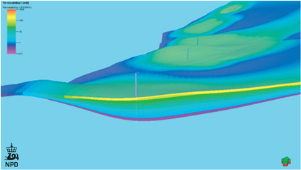
Fig-4-093
Porosity distribution near well 1
Three cases with different x-y permeabilities were run. Near well 1 the permeabilities vary from 0.14 mD in the bottom layer, to 199 mD in the top layer. The cases were run with the following model setups:
- Base model
- High perm model (permeability 20 times base case in top layer)
- Low perm model (0.5 times base permeability in all layers)
The results for the different models are shown in the figure, with three and five wells. The results show that in the base model with 3 mill Sm3/d, the reservoir can store 100 Mt CO2 before CO2 reaches the eastern boundary of the reservoir in the year 10 000. If extrapolated to 10 000 years of storage, the maximum amount stored will be about 75 Mt. With a high permeability layer at the top (high case), and 3 mill Sm3/d, the CO2 will reach the boundary in year 2416 after about 400 years of migration.
When the CO2 reaches the eastern boundary it is in gas phase and might migrate slowly upwards into the overlying Quaternary layers as discussed above.
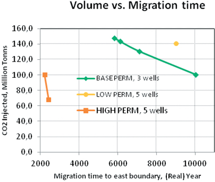
Fig-4-094
Volume of CO2 injected vs. migration time
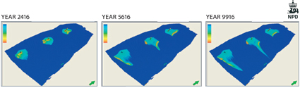
Fig-4-095
Volume of CO2 injected vs. migration time
Conclusions
The results show that the CO2 plume is distributed mostly in the high permeability (upper) layers of the reservoir.
With the base permeability model, about 100 Mt is the maximum storage capacity with migration for about 8000 years to boundary (year 10 000), if 3 mill Sm3/d is injected in three wells. Higher rates will give a shorter migration time. With the low perm model and 9 mill Sm3/d with five wells, the injected volume might be up to 140 Mt. A high permeability streak in the top layer will result in a short migration time, about 400 years. Low permeability and favourable communication reduces the risk of CO2 escape. The results indicate that migration velocities are slow unless the permeability and communication are very high, implying that subcropping aquifers could be of interest for CO2 storage.