The Utsira and Skade aquifer
Approximately 1 Mt CO2 from the Sleipner Field has been successfully injected annually in the Utsira Formation since 1996, proving that the formation is an excellent reservoir for CO2 storage. Due to its size, the formation has been regarded as attractive for storage of large volumes. However, the formation is part of a much larger sandy deltaic complex located at both sides of the UK-Norway boundary. The upper parts of this system are buried to less than 200 m below the sea floor, and the communication between the different sandy formations has not yet been studied in detail. In this atlas we present the results of an NPD study based on 3D seismic interpretation and biostratigraphy. The Miocene and Pliocene aquifer is subdivided into four major units which are in communication towards the west. The largest pore volumes in the system are in the Utsira and Skade Formations, which appear to be separated by a Middle Miocene shale in the eastern/distale parts. There is a regional dip upward towards the west, and consequently there is a risk that injected CO2 will migrate updip to levels which are too shallow to be accepted for storage. Three areas are assumed suitable for CO2 injection.
- The southern part of the Utsira Formation below approximately 750 m. This area has several structures which could accumulate CO2 and prevent it from migrating upslope. Large volumes can also be trapped as residual and dissolved CO2 in the aquifer.
- Volume in the NE part of the Utsira Formation. This part of the Utsira Formation is in communication with a delta which was built out from the Sognefjord area in the east. The top of the eastern fan reaches the base of the Quaternary and it has not been evaluated for storage.
- The outer part of the Skade Formation where it is sealed by Middle Miocene shale and could be trapped within structures formed by clay diapirism.
Pore volumes for this aquifer are presented together with storage capacities calculated for the three suggested sub-areas.
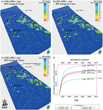
To estimate the capacity of CO2 storage in a southern part of Utsira/Skade aquifer, a reservoir model was built to simulate the long-term behavior of CO2 injection. The model covers 1600km2 in the southern part of the Norwegian sector. The study illustrates potential migration and forecast possible migration of CO2 from the Skade Formation into the Utsira Formation above.
CO2 injected in the Skade sand may penetrate through a intermediate clay layer into Utsira sand if the clay has permeability from 0.1 mD or higher. Approximately 170 Mt CO2 can be injected in Utsira-Skade aquifer within the segment model, with four horizontal wells injecting over 50 years, with BHP change of 10 bars, and with no water production. After 8000 years of storage, the dissolved part is nearly 70%, residual trapping is less than 1%, and mobile CO2 has decreased to 29% of the total amount of injected CO2.
These results are based on a residual saturation of CO2 of 0.02. If a residual saturation of CO2 is 0.3, CO2 trapped by residual mechanisms is 13% of total CO2 injected after 8000 years. Mineral trapping by geo-chemical reactions was not considered in the simula-tion, but will add additional storage capacity.
The NPD has calculated that 0.5-1.5 Gt of CO2 can be stored in the southern area of the Utsira-Skade aquifer, based on in house simulation calculations.
Fig-4-101
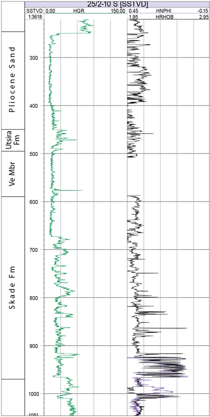
Fig-4-102
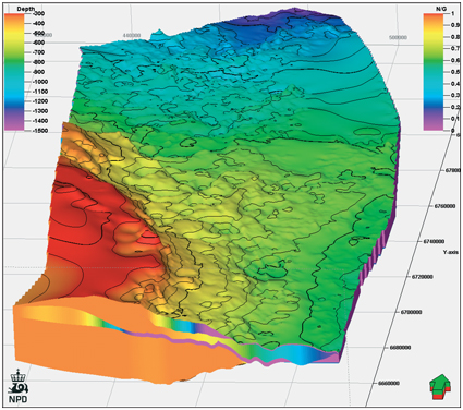
Fig-4-103
Cross section and top surface of the aquifer model.
Cross section shows net-gross values.
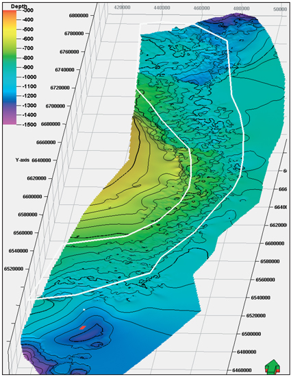
Fig-4-104
Top of Skade Formation. The white polygon indicates area which may be favorable for CO2 storage. Red dot shows Sleipner injection area. The grid squares are 20 km x 20 km.
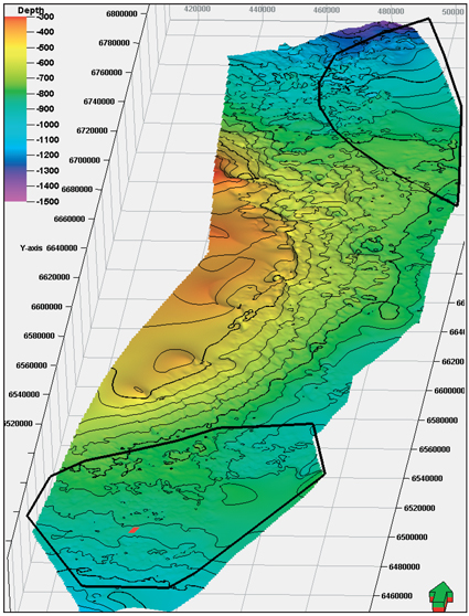
Fig-4-105
Top of Utsira Formation. The black polygons indi-cate areas which may be favorable for CO2 storage.
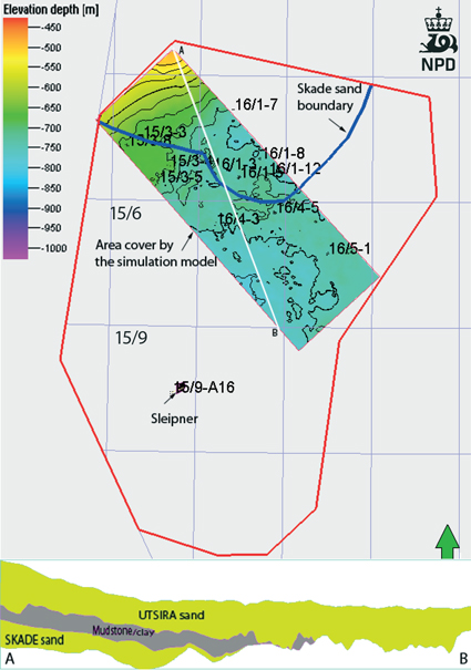
Fig-4-106
Red boundary defines the southern depocenter of the Utsira Formation. Skade Formation thins rapidly towards south and east, and is only observed as a few meters thick in well 15/6-7. The simulation model covers an area of 1600 m2 within the southern depocenter.
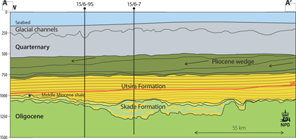
Fig-4-107
The Skade Fm, Lower Miocene, consists of marine sandstones (mainly turbidites) deposited over a large area of the Viking Graben (From 30/5-2 in the north, to 15/6-7 in the south ). The maximum thickness exceeds 300 m and decreases rapidly towards the south and east, where the sands terminate towards large shale diapirs.
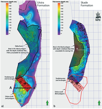
Fig-4-108
Thickness map (right) of Utsira and Skade Formations illustrat-ing the extent of the formations and the area which is above 700 meters depth and thereby unsuitable for CO2 storage.