4.2.2 Abandoned hydrocarbon fields
Storage in abandoned fields
The estimate of CO2 storage potential in the petroleum provinces is based on abandoned fields. This is in accordance with the Governmental policy that any negative consequences of CO2 storage projects for existing and future petroleum activity should be minimized.
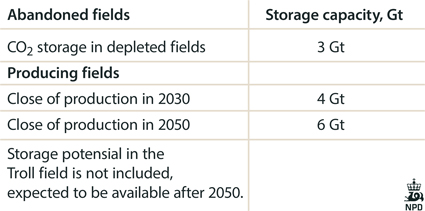
At the end of 2013 there are 12 abandoned fields on the Norwegian shelf. Of these three oil fields, four gas-condensate fields and five gas fields. Of the 12 fields, CO2 storage volumes have been calculated for nine. The chosen fields have been pressure depleted, and the calculations are based on material balance, taking into account the produced volumes of oil, con-densate and gas. Some of the fields are chalk fields in the Ekofisk area with low permeability reservoirs. To get decent injection rates, the wells need to be long with advanced completions. The fields have an EOR potential because they contain a rest of hydrocarbons that might be mobilized and produced during the injection. The CO2 storage capacity for today’s producing fields are estimated based on the close of the production year, and summarized for the years 2030 and 2050.
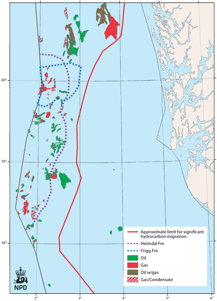
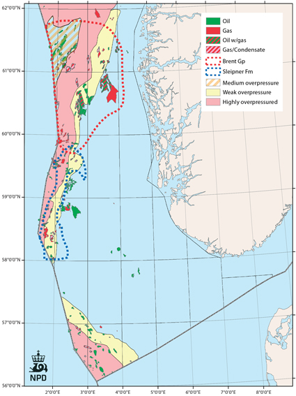
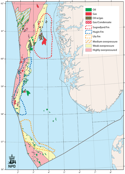
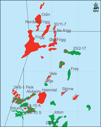
The Frigg field is studied in more detail and simulated due to its large storage potential. The fields and the main aquifers in the petroleum provinces in the North Sea are shown in the maps.
Many of the big fields in the Lower –Middle Jurassic Statfjord, Brent and Sleipner aquifers are located in areas with weak to moderate overpressure. In parts of the aquifers, the pressure has been depleted due to production. The highly overpressured parts of the aquifers (red color in the pressure maps) are not suitable for CO2 injection.
The Sognefjord and Hugin aquifers are hydrostati-cally pressured to weakly overpressured. The aquifers surrounding the big gas fields have been depleted due to gas production. The Ula Formation has oil fields which are weakly overpressured and relatively deeply buried.
The chalk formations in the southern part of the Norwegian sector have low permeabilities and have not been evaluated for CO2 storage. The large oil fields have interesting potential for use of CO2 to enhance the recovery (section 8).
The Paleocene and Eocene Ty, Heimdal, Hermod, Balder and Frigg Formations constitute a large hydrostatically pressured aquifer with both oil and gas fields. There is a significant pressure depletion due to gas production in Frigg and Heimdal. The storage potential in the aban-doned Frigg Field is presented in the following section.
The table shows an evaluation of storage potential in abandoned fields and in today's producing fields, based on close of production year.
Fig-4-145
Fig-4-146
Fig-4-147
Fig-4-148
Fig-4-149
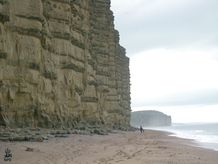
Lower Jurassic Bridport sandstone, Dorset, England. High porosity, good reservoir quality sandstone with calcite cemented beds and nodules, deposited in a shallow marine environ-ment. The thickness of the sandstone formation in this area is 40-50 m. The Bridport sandstone has been regarded as a reservoir analog for the Sognefjord Formation in the Troll area. Photo: NPD
FRIGG FIELD
The Frigg field was abandoned in 2004 after 27 years of gas production. The field was produced together with Nordøst Frigg, Lille-Frigg, Øst Frigg and Odin, which used the process facilities on Frigg. The field is located approximately 190 km west of Haugesund in Norway. Frigg is a transboundary field between Norway and the UK.
The reservoir consists of unconsolidated sand in the upper part. The properties are generally very good with porosity ranging from 27% to 32% and permeability from 1 to 5 Darcy.
The initial gas pressure was 197.9 bars at 1900 m MSL, and the initial aquifer pressure (Sele/Lista formations) was found to be 223.4 bars at 2191 m MSL. The water depth in the area is about 100 m.
The initial gas in-place volume was 247 GSm3, of which about 191 GSm3 has been recovered.
A CO2 injection study was done by the NPD in 2010 to see if the abandoned field and its satellites might be a candidate for future CO2 storage. A reservoir simulation model made by Total for the full field was used and converted to an Eclipse E300 compositional model. The model was matched both with regard to PVT and production history. The fluid was described with four component groups: CO2, N2+C1, C2-C6 and water.
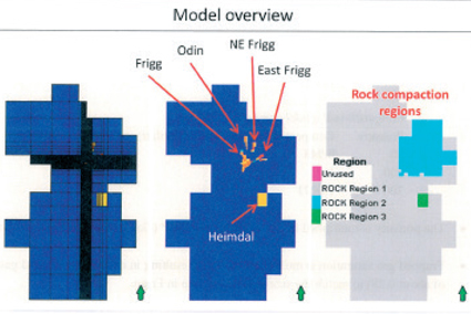
The simulation model included a huge aquifer around the Frigg fields. The model is shown in the lower right figure with grid cells, hydrocarbon accumulation and rock compaction regions. The main cases run were the following:
- Production of remaining gas together with CO2 injection
- Injection with closed aquifer, no gas production
- Injection with leaking aquifer, no gas production
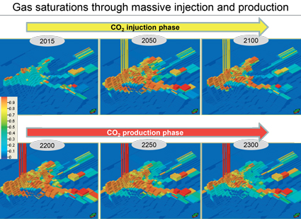
In case 1, 10 mill Sm3/d of CO2 was injected for 55 years from one well in the aquifer, and remaining methane gas was produced from the top of the Frigg field. In cases 2 and 3, CO2 injection with 10 and 50 mill Sm3/d was applied in an open aquifer. An open aquifer was simu-lated by producing water in the corners of the aquifer, thus keeping the pressure increase quite slow. The results are shown in Table 5.2.1. The range in methane gas volume produced is due to the uncertainty in trapped gas saturation, where low values of trapped gas correspond to high volumes produced. Base case trapped gas saturation (Sgr) is 0.28 and gives 0.3 Gsm3. An Sgr of 0.14 gives 18.8 GSm3.
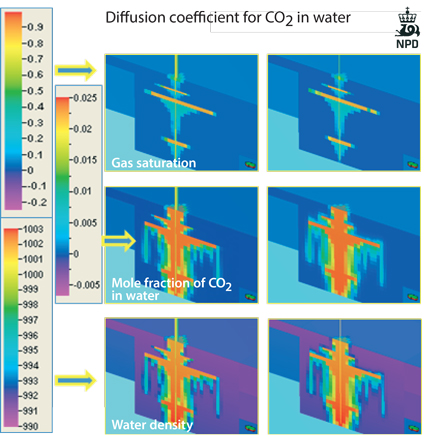
In cases 2 and 3, pressure builds up from about 183 bar in Frigg, which is about 20 bars below initial pressure, to 208 bars in case 2 and 278 bars in case 3. The behaviour of CO2 in the formation water has a long-term effect, as more and more of the free CO2 will dissolve. This leads to heavier formation water which will start to move downward as shown in the figure.
Fig-4-150
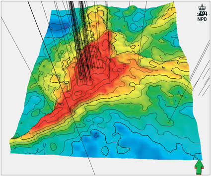
Structural map of the Frigg field with all wells
Fig-4-151
Frigg field with satellites. Hydrocarbon fields in the Frigg area
Fig-4-152
Conclusion
The Frigg field has a large potential for CO2 storage due to remaining gas in the field itself and a huge aquifer that is connected to the field. The simulation shows that there is a higher potential than what is simulated if the pressure increase is compensated with more water production out of the aquifer.
Some thought should be given to the abandoned wells on the Frigg field and its satellites as their sealing capacity for CO2 has not been studied in detail. If storage is implemented in Frigg, integrity studies and monitoring of the old wells will be an important issue.
