5.2 Storage options in the Norwegian Sea
In the Norwegian Sea, the general conditions are met in the Trøndelag Platform including the Nordland Ridge and in the Møre Basin. Potential CO2 storage in the shelf slope and deep sea provinces of the Norwegian Sea has not been evaluated (Cretaceous formations, section 4).
The aquifers in the Trøndelag Platform have been studied by compilation of published maps, new seismic mapping, well studies and well correlation. The Draugen area and the Nordland Ridge have good data coverage with 3D seismic and several wells, while the remaining area has 2D seismic data and a few exploration wells.
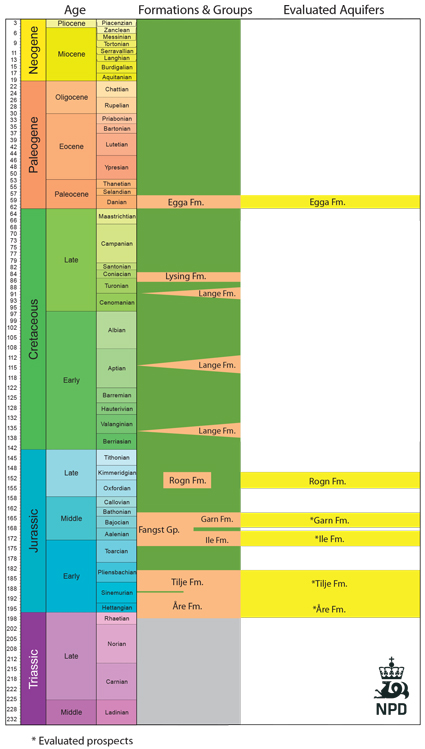
As described in section 4, the Jurassic succession in the Norwegian Sea Shelf is thick and contains several aquifers with storage potential for CO2. The Halten and Dønna Terraces are important petroleum provinces. The hydrocarbons in these provinces are believed to be generated from Jurassic source rocks, mainly from the Spekk and Åre Formations. In the Trøndelag Platform, the Jurassic source rocks have not been buried deep enough to reach the oil and gas maturation window, and the hydrocarbons occurring here have migrated from the deeper basins and terraces. The approximate limit for hydrocarbon generation and migration is indicated by the red line (page 94). Some oil and gas may have been generated in the deepest part of the Helgeland Basin, although so far there has been no exploration success in this area.
In the petroleum provinces (west of the red line), exploration and production activities are expected to continue for many years to come. The most realistic sites for CO2 storage in the petroleum provinces will be some of the abandoned fields. Consequently, an indication of the storage capacity of the fields has been given, but no aquifer volumes have been calculated for this area. Some of the oil fields are considered to have a potential for enhanced oil recovery (EOR) by use of CO2 (section 8). A certain amount of the CO2 used for EOR will remain trapped.
In the eastern area, all the large aquifers have been selected based on the established criteria (section 3.3), and storage capacity is estimated by the method described in section 3.4.
Fig-5-053
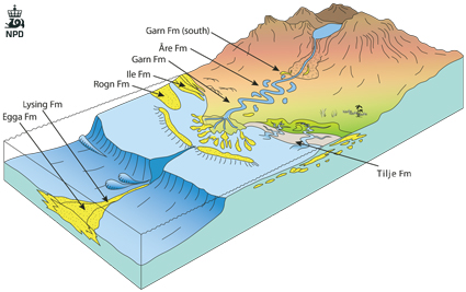
Conceptual sketch showing location of aquifers relative to depositional systems
Fig-5-054

